Claviger
Aspiring Student
- Joined
- Jul 25, 2014
- Messages
- 6,934
- Location
- Olympia Washington
- Ride
- '21 Z H2, '14 R3R, '02 Daytona 955i
Finally found the manufacturer of the screen I was using, this one:

I bought it 2nd hand from a French Captain on ebay, but motoplast is smart enough to embed their business card on the inside of the fiberglass area and I had the foresight to take a picture before I painted it, finally found the picture.
motoplast-gregori.de
350 euro for the fiberglass part
100 euro for the MRA screen
Inquiry sent, shall know soon if they're still manufacturing them.
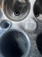
Looking back through some unshared pictures, I also found some valve seat pictures for the 40mm Ti intake valves. The cut goes like this:
45 degree seat
That's it, no throat cut, no top cut, no backcut on vavles, just a straight 45 degree seat cut and called it a day. Looking at it, it's apparent the head was ported before seats were installed; there's not a single mark on the seats in the throat, they weren't ever worked. or shaped, just straight throat and the bowl is curved to meet the seat.
- So, for any 265 kit owners, there's your extra flow to be had if you know what you're doing with valve seats and valve back cuts.
- No de-shrouding was done either around the seat in the chamber, so there's some more gain.
A project for future me...
I bought it 2nd hand from a French Captain on ebay, but motoplast is smart enough to embed their business card on the inside of the fiberglass area and I had the foresight to take a picture before I painted it, finally found the picture.
motoplast-gregori.de
350 euro for the fiberglass part
100 euro for the MRA screen
Inquiry sent, shall know soon if they're still manufacturing them.
Looking back through some unshared pictures, I also found some valve seat pictures for the 40mm Ti intake valves. The cut goes like this:
45 degree seat
That's it, no throat cut, no top cut, no backcut on vavles, just a straight 45 degree seat cut and called it a day. Looking at it, it's apparent the head was ported before seats were installed; there's not a single mark on the seats in the throat, they weren't ever worked. or shaped, just straight throat and the bowl is curved to meet the seat.
- So, for any 265 kit owners, there's your extra flow to be had if you know what you're doing with valve seats and valve back cuts.
- No de-shrouding was done either around the seat in the chamber, so there's some more gain.
A project for future me...
Last edited: