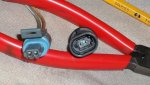
I am realy interested in the OBD scan guage stuff as I was think I could add another plug under the seat for it while keeping one for the TUNE BOY software link cable. I link up many times and would not want to keep unhooking the scan guage.
Thanks for your input.
I am not sure how the Scangauge is gonna like sharing the data stream with TUNE BOY. From my experience this is not a doable thing. What you may be able to do tho is splice it in in to the data line with a double pole, double throw switch, so that as you open the Tune Boy you close the Scangauge circuit.
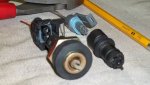
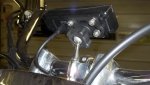
The mount I used was a "Tech-connect Accessory Mount" from Kuryakyn, although I'm sure others are avail for less money. I did disassemble the Scangauge so that I could give it a little weatherproofing and also bolt it fast right through the back cover. The mount has a thumb nut that makes it easy to remove if I know its gonna rain or get really soaked for any reason. It has been wet, but not soaked and I haven't had any problems yet. I did change the power supply at the OBD connector from B+ to ignition 1 because I didn't want it powered all the time.[/QUOTE]
Thanks I guess to eliminate the sharing problem I will just use the OBD plug that way I have to unplug it when using tune boy. Where did you order it from?
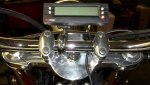
I can see where the water proffing would be important maybe I can fit the bugger in the cock pit Gary designed but then I guess I should put it on my other stead as Gracie already has a quad gauge with most of these functions in the cockpit Gary built.
The quad gauge in the center has Water temp, oil pressure, Fuel level in % and charging voltage. which works well the compass /clock gauge I have to figure out how to set and calibrate accurately and well the A/F meter with data logging capability. I have to work on this because its a little different then the Weggo III unit I use on the Millenium Falcon.
Gary was a electrical engineer and it is work figuring out how he set this bike up. So far so good I would say he was definetly headed in the right direction. The added bonus is most people would look at it and decide not to steal it because they would be afriad they could not start the bugger let alone understand the system

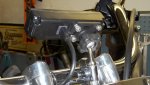
SO It would look like some of the systems in the scan tool would be duplicated but still worth looking into for sure.