P0122 error code MAP

raul_86

.020 Over
Joined
Mar 14, 2025
Messages
14
Ride
Triumph rocket III
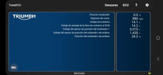
hi everyone, found out that my Rocket III roadster 2014 have a different map than the original 20776Map.hex, my question is this could affect the voltage in the primary tps sensor ?

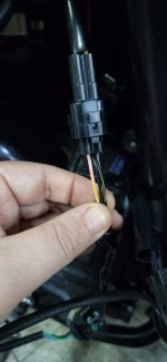
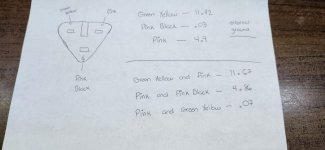
i swap the entire harness threw a lot of codes and erase it with tune ecu and just leave P0122 change the sensor and doesnt work properly i twist the throttle and dies.

or maybe i need a new ECU

any ideas, opinion are very welcome
 
P0122 low tps voltage
i would say you need to check to see if you have the 5volt reference voltage

#3 GREEN/YELLOW TO A10 ON ECU TPS RETURN SIGNAL
#2 PINK/BLACK TO ECU A07 GROUNDS
#1 PINK TO ECU A01 5 VOLTS REFFERRENCE

the way to check
UNPLUG AND SEE IF IT HAS 5VOLTS***** YOU CAN CHECK #1 PIN (PROBE RED) TO #2 PIN (BLACK PROBE) TO SEE IF YOU HAVE VOLTAGE/GROUND

IF YOU HAVE TUNEECU (SORRY caps) then check the voltage with that
you may not have the tps clocked in the correct position
hth
edit
sorry this info for 2007 classic
may be the same
 
P0122 low tps voltage
i would say you need to check to see if you have the 5volt reference voltage

#3 GREEN/YELLOW TO A10 ON ECU TPS RETURN SIGNAL
#2 PINK/BLACK TO ECU A07 GROUNDS
#1 PINK TO ECU A01 5 VOLTS REFFERRENCE

the way to check
UNPLUG AND SEE IF IT HAS 5VOLTS***** YOU CAN CHECK #1 PIN (PROBE RED) TO #2 PIN (BLACK PROBE) TO SEE IF YOU HAVE VOLTAGE/GROUND

IF YOU HAVE TUNEECU (SORRY caps) then check the voltage with that
you may not have the tps clocked in the correct position
hth

this are the voltage,i try tu put it on in different ways like the secondary that you need to rotate it but theres only one position.

the new harness is different dont need the fly lead with the color you tell me, the gps sensor plugs in directly.

attach a photo of the colors and use a multimeter to reads the voltage and only gives 4.8v

pink yellow

black

black yellow
 

Attachments

  • WhatsApp Image 2025-03-18 at 7.39.56 PM.jpeg
    WhatsApp Image 2025-03-18 at 7.39.56 PM.jpeg
    56.7 KB · Views: 9
  • WhatsApp Image 2025-03-21 at 7.33.37 PM.jpeg
    WhatsApp Image 2025-03-21 at 7.33.37 PM.jpeg
    58.7 KB · Views: 9
4.8 is fine
Did you check the ground
You will have to probe #3 to read the voltage to the ecu A10
I will be at the shop after ride all info is there.
 
well ido not know where my post went (saturday)
any way i did some checking and it went something like this
#3 pink/yellow a10 ecu
#2 pink/black b20 ecu
#1 pink b01 ecu

the only colored wires i could find like you posted were to a speed sensor
i think you have the wrong connector
it is possible that i am wrong.
thanks i was chating with RIIIR turbo and my bike doesnt have a flylead that goes to the GPS sensor and its connected to the TPS sensor so the colors changue,

if you see the colors of the plug direct to yout harness match with mine.

how do i check the signal of the ECU maybe the ECU is the one that doesnt send the signal and the tps its okay.

Thanks
 
Well the bad news is my internet is down for the day
Good news my phone is now working lol
RIIIR is an expert and explains things very well.
We really need your engine number to have the correct wiring diagram. Also would you happen to have or can get the engine number of the wiring diagram you installed.
Does your bike have abs?
You need to locate the tps connector and see if it is hooked up got an ides but need my internet to work.
 
Ok internet up and running
talking strictly about the tps throttle potentiometer sensor because that is what trigger the code p0122
i looked at a lot of wiring diagrams and they had in common the pink wire for 5 volts reference voltage from the ecu.
the pink/black for ecu ground
and for the signal wire back to the ecu it was either pink/yellow or gray/yellow depending on the wiring dia you looked at.
being that the code p0122 is low volts then i think that the connector is not hooked up.
1st you check you need to see if it has close to 5 volts on the pink tps wire.
2nd you need to check the pink/black wire to see if it is ground.
3rd if those two check good then while it is hooked up you probe the wire (pink/yellow or the gray/yellow) and monitor the voltage while working the throttle should be about .72 to about 5 volts.
ps
made a mistake earlier don't know where i got the color green/yellow from
 
well ido not know where my post went (saturday)
any way i did some checking and it went something like this
#3 pink/yellow a10 ecu
#2 pink/black b20 ecu
#1 pink b01 ecu

the only colored wires i could find like you posted were to a speed sensor
i think you have the wrong connector
it is possible that i am wrong


to check the ground
Ok internet up and running
talking strictly about the tps throttle potentiometer sensor because that is what trigger the code p0122
i looked at a lot of wiring diagrams and they had in common the pink wire for 5 volts reference voltage from the ecu.
the pink/black for ecu ground
and for the signal wire back to the ecu it was either pink/yellow or gray/yellow depending on the wiring dia you looked at.
being that the code p0122 is low volts then i think that the connector is not hooked up.
1st you check you need to see if it has close to 5 volts on the pink tps wire.
2nd you need to check the pink/black wire to see if it is ground.
3rd if those two check good then while it is hooked up you probe the wire (pink/yellow or the gray/yellow) and monitor the voltage while working the throttle should be about .72 to about 5 volts.
ps
made a mistake earlier don't know where i got the color green/yellow from

Well the bad news is my internet is down for the day
Good news my phone is now working lol
RIIIR is an expert and explains things very well.
We really need your engine number to have the correct wiring diagram. Also would you happen to have or can get the engine number of the wiring diagram you installed.
Does your bike have abs?
You need to locate the tps connector and see if it is hooked up got an ides but need my internet to work.


yes is abs
Roadster 2014
the engine number is 3622018

hope the internet comes back soon
 
to check the ground


yes is abs
Roadster 2014
the engine number is 3622018

hope the internet comes back soon

thanks for your help, really im not an expert but i try my best

the first block of the sheet its with and external ground and then the other its mixing with the others

the pink and green yellow its the signal from the ecu of the voltage that we use to adjust the tps sensor, because when i try to adjust them the primary only does .15 to .20 (correct me if im wrong)

and the secondray gives the right number 5 to 7 and then adjust to 6 volts.

talking with a buddy of mine he says maybe is the computer some resistance that maybe brakes and the ecu doesnt send the right signal for the tps.
 

Attachments

  • wiring .jpeg
    wiring .jpeg
    69.7 KB · Views: 3
Back
Top