I need a Gear Position Sensor GURU for this one

So an 16 sensor in the 16 engine, an 05 external portion of the sensor and 05 harness, and an 05 ECU is the current hardware situation right?

If that's the case, the internal portion is also different, a simple swap of the external sensor portion of the GPS system will not work. You'll need to swap out the internal portion as well.

Alternatively, you could install a GIPRO to trick the ECU into assuming it's in 3/4/5 all the time. This will at least keep it driving in the good ignition tables.

16 sensor
P0705 - Gear position sensor circuit malfunction

Check final post here for update procedure to the new improved part, which, may fix your issue:
Problems with gipro and gear position sensor


Thanks ALL for your input.! I may have stumbled upon a fix but I won't know til I try it out. After a closer examination of my 05 gear position shaft, I noticed that there is a tiny spring recessed in the hole. I'm guessing that this spring is what makes contact with the contact pods in the original 05 GPS. With the 16, the GPS sensor has a protrusion rod that fits into this hole. Going to pull the GPS and install the spring into the shaft hole and see what happens.
 
and if that does not work u can come up with another idea:laugh::laugh:
 
From memory (my bikes 05) the gear sensor is only two wire the sensor has a series of resistors (i know as I measured them when I first got the bike) that tells the ECU which gear the bike is is, but only 1, 2or3, 4and5. So three inputs.

Think the R3R has a gear indicator (dont know for sure) but the sensor will be completely different.

I will stand corrected but I dont think you'll find a "work around" for this one sadly, the ECU's are different too.

The Roadster GPS is totally different than the older ones like 05.
It reads back 7 positions that I'm aware of (1-N-2-3-4-5-6) when mated with the Roadster ECU as it's used on other models with 6 gears. Don't know how many the 05 read back has but I'd guess 4 or less.

Initially the Roadster ones were a 3 wire (1 more wire than the 05 etc), but these had a fault.
Around 2013 they updated the part # to a 4-wire GPS for Roadsters.

The new GPS part comes with an adaptor sub-harness for the new GPS to plug into 2010-13ish Roadsters' harness. Plus you have to rearrange pins a little in the clocks when fitting this one, to be rid of that fault.

However the newest Roadster harnesses have a 4 pin female to receive the new GPS sensor, so no need for the adaptor like the 2010-2013 bikes need.

What went wrong with your '16 GPS?
I have a couple of spare Roadster GPSs floating about.

Edit: OP didn't specify the thing was being connected to an 05 harness with 07 ECU.

Is the 16 engine in an older chassis, or is in the 16 chassis with ABS and Roadster clocks?

Thanks ALL for your input.! I may have stumbled upon a fix but I won't know til I try it out. After a closer examination of my 05 gear position shaft, I noticed that there is a tiny spring recessed in the hole. I'm guessing that this spring is what makes contact with the contact pods in the original 05 GPS. With the 16, the GPS sensor has a protrusion rod that fits into this hole. Going to pull the GPS and install the spring into the shaft hole and see what happens.

ok Johnny Cash that will make it easy:D

Breaking news from Johnny Cash (Turbo200R4,I'm not sure about the J.C. reference)!!!

#1...The spring from the 05 gear position shaft did the trick. I can get a neutral light now so I know that the spring was the key to THAT particular issue, however the 7 positions that Kenneth67 brought up is dead on. It doesn't sense neutral where neutral is supposed to be. I have to play with the shifter to get the light on and when I release the clutch you can tell that that the gears were almost engaged. I can hear the clank of the teeth.
Hopefully when I'm in higher gears it will sense 4th or 5th.
 
do u mean u have to put pressure on the shift lever to make the light come on?
if so can u remove gps bolts and rotate slightly so as to see correct position and then find a way to lock it down. as a last resort u can install a button switch and ground the neutral wire.before i would check with a fused wire.
 
From memory (my bikes 05) the gear sensor is only two wire the sensor has a series of resistors (i know as I measured them when I first got the bike) that tells the ECU which gear the bike is is, but only 1, 2or3, 4and5. So three inputs.

Think the R3R has a gear indicator (dont know for sure) but the sensor will be completely different.

I will stand corrected but I dont think you'll find a "work around" for this one sadly, the ECU's are different too.
Do you happen to have the resister values you measured on your '05? I'm having issues with mine and want to create a dummy "sensor" for testing
 
I can't remember perzactly, but I do have a 2015 engine in a 2005. I have the 05 ECU, etc. etc. I had to switch the GPS, and you do have to switch the small parts. Also I had to use a couple of spacer washers under the bolt flanges of the 05 sensor, on the 2015 engine. Works fine. Someone that knows better will chime in soon I think.
 
Running a 16 engine with a 10 ecu, loom & gauges in 9 bike.
When I bought the engine the gps was already in there (got no idea if it was changed out) but everything just plugged in & all worked...got lucky I guess 👍🚀
 
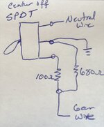
Well I pulled it apart again and did some testing, Black/White wire is neutral switch (ground this wire for neutral) and the black wire is the gear position (different resistance for each gear). The approximate resistances for each gear is 1st=85Ω, 2nd=180Ω, 3rd=380Ω, 4th=680Ω, 5th=1200Ω and the nonexistent 6th=2740Ω. I am having the same issue motioned where my indicator shaft has lost the roll pin connection to the shift drum and is free wheeling. I made up a temporary (which may just stay permanent) switch to select 1, 4 or N using a SPDT center off switch and a couple resistors (see hand sketch diagram). With switch down it simulates being in Neutral by grounding the black/white wire, center off position the ECU sees 4th gear through the 680Ω resister to ground and in the up position it parallels the 680Ω & 100Ω resisters to ground (about 87Ω) causing the ECU to see 1st gear. I think I will mostly use the N & 4 positions unless maybe if running around town...
 

Attachments

  • IMG_0723.jpg
    IMG_0723.jpg
    111.3 KB · Views: 10
Back
Top