Richard. I've had a look at your earlier video;
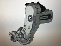
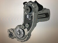
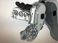
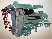
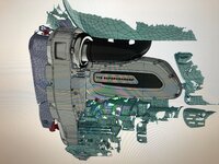
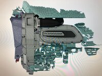
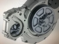
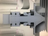
And you seem to be doing a pukka engineering job here, once again. Things have really come along the last nine months, despite COVID-19 and other challenges, when comparing the 3D screen-dumps included here to the prototype pieces featured in the video. You probably need to consider an update on that. Please include some 3D stress simulations using the software's FEA features, assuming that you are using SolidWorks® or similar.
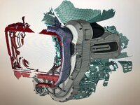
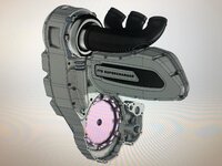
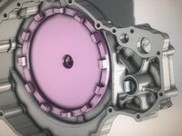
There is only about 75 mm (3") clearance between the oil cooler screen and the front tire's rear edge. How much of that will be lost when the assembly is fitted, complete with the clutch slave cylinder and possibly another cover over that?
I am hoping that you are going to offer this in three stages since I, for one, do not intend major heart surgery on my Rocket any time soon - meaning to the extent of installing low compression pistons, etc. I would not object to cams, though, since we will already work on the clutch and water pump. Something along these lines, I would think;
Stage 1. 8-10 psi. Stock compression and clutch. Maybe mild cams. 230-250 rwhp. Just enough to scare the local Tupperware torpedoes off for good.
Stage 2. 14-16 psi. Lowered compression, beefed-up clutch, wilder cams. 280-300 rwhp. One up on that blown Suzondayamasaki that sputters by every so often.
Stage 3. 14-16 psi, but the Full Monty. Stage 2 plus stronger con-rods, balancing, optional blueprinting, optional methanol/water injection, intercooler on the lefthand side (in full view), larger headers. 330-350 rwhp. With optional 'Street Outlaw' wheelie bar, of course (-:

") Well done!
Well done!
 .
.